What started as repair of my Bushnell scope, resulted in an idea that I thought may be advantageous to all IHP air gun owners.
Incident:
- IHP Guns don’t have any provision to mount a scope.
- Predominantly, the ‘U’ and ‘I’ (Rear and fore sight) type of aiming, although profound since early invention, seemed the most used method of aiming, and the only next solution was the optical scope.
- Moving targets were pretty tough to shoot with this type of aiming.
- No other alternative existed apart from jumping a floor higher to optical scope, which would cost more than the gun itself.
- In case, people did get into Peep sight, it is increasingly difficult to aim fast and shoot at moving objects with the Peep sight.
- I wanted to have another type of aiming system, apart from the peep sight type, which could help in aiming moving targets, minus the optics.
- I wanted to make it more of a ‘home’ project using cheap and easily available stuff, found all around us.
The concept that I thought of was to have two cross wires, one in the front and one in the back. This new concept works like this. There can only be one correct line that joins the centers of two cross wires, and if this line is parallel to the barrel (zeroing), it should be a perfect shot. The front cross wire can have ‘knots’ which may be close to the ‘mil-dots’, thus allowing the shooter to adjust the rear cross wire to match the required ‘mil-dot’ for distance based accuracy.
For more precise aim, I thought of having a ‘+’ cross-wire in the front, and an ‘X’ in the back. This way, the shooter can easily match the two to get something like a ‘*’, which means that the line of aim is accurate.
An imagery of the idea is as such:
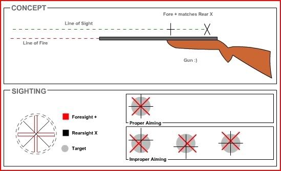
After this detailing, and with the concept in place, I started off making what I thought would be a new way of sighting – faster, simpler and accurate at very low cost. Best part is that one could make it him/herself, improvisation and repairs would be of low concern.
Kick-Off:
At the Kickoff stage, I assembled my notes, tools, available ‘garbage’ around the house – which became my raw materials. All these are easily available and if you don’t find them lying around the house, you can buy them sub-100 bucks
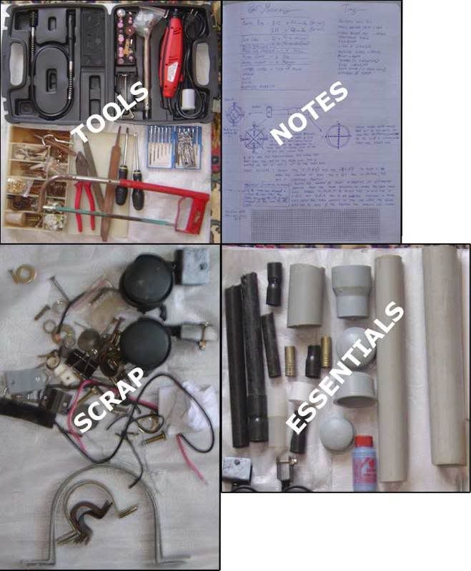
Under the essentials, you will see the basic raw material that I used in making the ACK_Scope.
- Plastic pipe of 50mm and 40 mm dia X 1 feet each.
- 1 inch plastic pipe
- End caps for the pipe – to be used as a scope bikini X 1 each
- Plastic Pipe glue
- Pipe adapter – 50mm to 40mm
- Metal clamp – 2 Big
- Copper wires – Thin & Thick (or silk or dog hair, etc) for cross wires
- Screws, Nuts, Bolts…
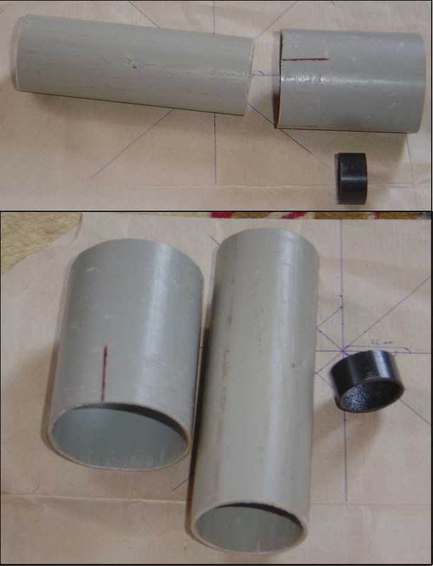
I calculated that the rear pipe and the front part should be in the ratio of 10:7 for best view. By this, I cut off about 10cm and 7 cm of the small and big pipe, respectively.
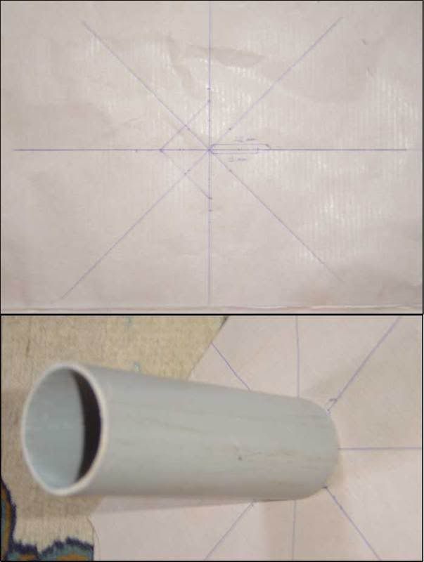
You will now have to mark the diameter markings for placing the + and the X. For this, take a sheet of paper and put in a graph of the + (and/or X) and mark 20mm and 25mm from the center – the point of intersection. Place the pipe vertically on this graph with the pipe edges sitting on the 20mm (for the small pipe) and 25mm (for the big one) marks that you made. Use the intersection lines of the graph to make corresponding marking on the pipe. For the smaller pipe, you would need to mark both the + and the X corresponding points. This is because I thought up of an ingenious system to make the rear X adjustable for better zeroing. I will explain this later. With this, you will have:
1 Big pipe of 7 cm with 4 markings on its outer rims – both ends; and one smaller pipe with 4 markings on one rim end and 8 markings on the other.
The smallest pipe- the black 1 inch pipe will hold the rear sight ‘X’. A length of about 1 cm of this pipe should be good.
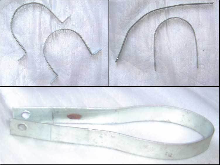
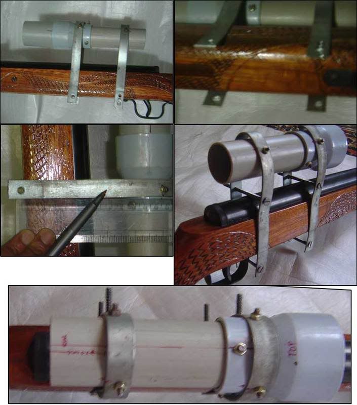
Here is making the clamp to hold the scope to the rifle, since IFG guns do not have scope mounting facility. You will need two large size clamps, made of some string metal. This is mostly used for large drain pipe fixing on walls. Straighten the end, open it and then bend it as shown. Basically, one clamp should have about 44 mm of gap (sits on the adapter) at the top end and the legs should try to meet at the bottom. The other with about 40mm clearing.
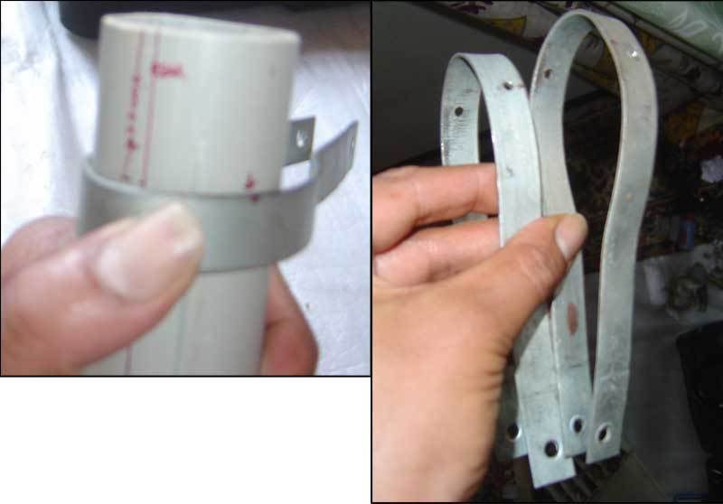
You will now have to place the pipe/adapter inside the clamp and make adequate markings for boring holes to provision fixing of the pipe onto the clamp. I have marked the hole where the clamp touches the pipe/adapter best. For the small pipe, you will have to leave about 1.5 to inches from the end, to allow provision of the eye-piece and the scope cap.
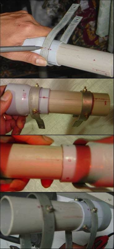
Drill holes and now fix:
1. The pipes to the adapter.
2. The pipes and adapter to the clamp. Note that the holes have been marked, drilled, and fixed sturdily with short bolts.
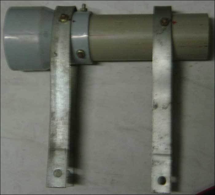
Now, we have the basic setup done. It is best to mount the clamps onto the rifle, and check if the holes at the ends of the clamps match well. Sometimes, small re-bend may be required if the scope is sitting on an offset. You may even have to drill holes thru the clamp end if the holes don’t match.
You will see that I have fitted the adapter to the short pipe, with the clamps tightly sitting, all with short bolts.
While setting the scope clamp on the rifle, see the clearance that I have taken between the rifle body and the scope. In this area, mark corresponding holes and drill thru to place another set of bolts. For the IHP MOD 35, 8 cm from the bottom hole should suffice. You will now have each clamp holding onto the rifle with two bolts, one above and one below the rifle. You can adequately tighten the bolts to ensure zero movement.
You should also note that I had to drill additional holes on one of the clamp ends to allow for the lack of precision of bending the clamps.
When you look at the rifle and scope setup from the top, you may notice, as I did, a slight shift in the vertical alignment of the rear scope pipe (small). For this, I had to make a correction of about 2.5 mm to match the lateral planes of the rifle and scope. If you don’t do this correction, the + and X may be slightly rotated, in the end.
Now comes the front part – the larger pipe that holds the ‘+’.
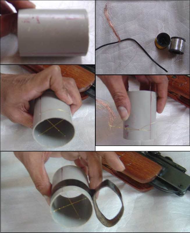
You can use copper wire, as shown, or silk, or dog hair, or gold embroidery thread, as I did. If you use copper wire, you will have to strand the outer casing by cutting the plastic in line with the wire. This will ensure that the copper wire does not get damaged, which may happen in normal types of clipping.
Make small hole at the end of the big pipe (about 1 inch from the end), along the four lines that you had marked. Pass the wire thru nice and tight and make any good fishing know to hold it in place securely. You can now wind some tape around the outer part of the cross wire thread/wire to ensure less damage. I have also put in knots on one of the lines of the cross-wire. This will act as mil-dots.
The front + is now ready. You can carefully fix it to the front of the adapter with some pipe sealant to ensure it sits nice and tight. Be very careful while doing this and ensure that your best judgment prevails in proper aligning.
Here comes the back X part on the smaller pipe.
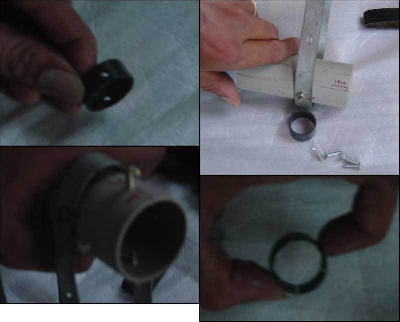
Make four small holes on the smaller black piece of 1 inch pipe. This should, as in all cases, match the screw/bolt threading that you plan to use. Apart from this, you will also have to mark the inbetween divisions on the small pipe, which will hold the rear cross wire. I used a small file to mark a notch, so that the cross wire sits nice and tight without slipping. Once you have wound the cross wire well onto the small black pipe, put in adequate tape to secure the outer part. You will now have a small 1 inch pipe of about 1 cm long with four holes and a cross wire which is sitting exactly inbetween the 4 holes.
Mark 4 holes - 2 vertical and 2 horizontal, on the end of the smaller (40mm) tube. The holes should be about 1 inch away from the end of the pipe. The plan is to have the small black piece (with cross wire) inside the center of the back end of the rear tube, with 4 screws holding it in place, so that the 4 screws can be used to shift the inner black pipe up/down/left/right to small distances, which may act as additional zeroing measures.
In this final step, you will see the rear ‘X’ I the small back pipe sitting inside the rear end of the 40mm tube. Thru sight on the other end shows the ‘+’ cross wire on the front end of the larger 50mm pipe. If you can get this to align, as mentioned in the concept, rest assured you have a clear shot.
Since you have a 50mm pipe at the front, the area of visibility is pretty good. Matching the cross wires is easier and much more accurate than matching a ‘v’ and ‘i’ or anything else…
Initially, it took me a few shots to get used to this, but by about the 20th shot, I felt this to be much faster in aiming.
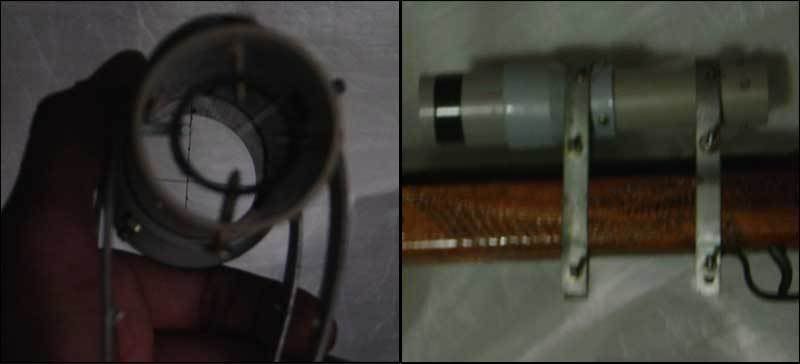
Presently, I am finding some other material for the rear cross wire (X) since it blurs out at closer distance. After that, I will paint the entire stuff once again and post it with grouping samples.
I am sure that anyone else like Mack The Knife, etc, with a little bit of skill and idea in using materials can make something much better, but this is a start. Let us all input and make a innovate revolutionary targeting system – the essence being simple, easy to make (DIY), low-cost, and one that can fit on an IHP
... all the best. If Bushnell wants to contact me to take this idea, they are most welcome


