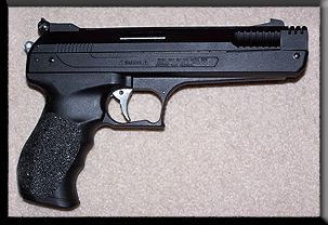
Scope Repair Update....
With some free time, and waiting for the Bluing liquid, I decided to have a second look at my scope, which incidentally had the same
problem of the magnification ring not moving, and one of the rear parts had skipped a thread.
I was trying to get the scope to US and have it checked/repaired by Bushnell, but I did not get any response from them for the emails
sent. Furthermore, the cost of shipping to US was more than the cost of the scope that I bought it for, and hence, I had nothing to lose
with a little R & D.
So, what I did was get the proper tools to completely dismantle the scope parts and decided to check what I might find wrong. I looked
into some of the scope parts and diagrams on the web, and as I started to dismantle the scope, I got a pretty good idea what I was
removing and how it works.
I also checked with the two domestic hands at home. and one of them mentioned that a nephew who visited my house in my absence
took the liberty of 'checking' the scope that was fitted onto the HW77K. He seems to have injured the scope, because the maid did
say she heard a banging noise, after which he immediately kept it back. (No more guns in the house unless I get a lockable gun rack!)
After carefully removing the parts, and successfully breaking the cross hairs out of sheer sweat-based accident (when I dropped the
screw driver right on the cross hair, I was now faced with two problems:
1. The magnification would not work
2. The cross hairs were kaput!
Bracing my courage with a couple of beers, I continued and removed the rest of the parts carefully. I was challenged by a particular
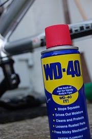
rear fitting that would just not turn. I was a little afraid to spray WD40 directly onto it, and then decided to apply a small bit using a
cloth. In the mean time, an ably well built friend of mine came home to visit me ... and what are friends for

After letting him know exactly what I wanted, he removed the piece in the first attempt. Now all I had to do was remove the remaining
parts, find out what makes the magnification ring immovable, fix it, and make new cross hairs.
The cross hairs had me thinking for a while, when I thought I would use thin copper strands from electrical wire. But they were too
delicate and the slightest bend or pressure made them go all awry. It was time for my dogs' pee and they were running all around me.
A thought struck and I plucked two strands of hair from their tail, which wa straight and long enough. They matched the leftover of the
original cross-wires in size - thickness (approximately) and color. With a little bit of super glue, the cross hairs were placed, and it
looks pretty wkk now. If I had probably not mentioned it, it seems hard to find out

As I removed the magnification ring (Part A), one finds the first inner Magnification ring part (called Part B). In this, I found out that right
below where the screw of the magnification ring sits is a part that has a groove similar to this:
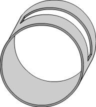
Notice the
cut into part B. Right below this part is the actual magnification part (Part C), that has another groove like this:
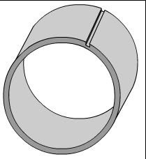
Within this groove sits the screw that passes thru the outer Magnification ring (Part A), then the first inner part (Part B) and finally sits well in the groove of Part C.
The screw is somewhat like this:
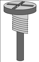
The first part of the screw which has the threading sits in the outer Magnification ring (Part A) snuggly screwed in. The rest of the small rod like protrusion goes in thru the Cut in Part B and then sits in the groove of Part C. Thus, when the outer ring is moced clockwise/counter-clockwise, the rod protrusion of the screw moves freely thru the cut in Part B and then actually moves the Part C in the same direction. The screw sits inside the two inner rings (Part B and Part C) like this:
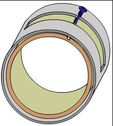
Note: the threading seen above is actually sitting well in the outer magnification adjustment ring (part A), which is seen on the outside, and used to control magnification
In my case, the cut in Part B had its shape distorted. That is, the distance between the length of the cut was not proper, and the center of the cut had moved in closer to the walls of each other. Boy, I sure am having a rough time explaining all this! This prevented the smooth flow of the screw-rod, and that was the problem. Probably, the boy much have struck the scope rear head to something, and the cut may have closed up.
I tried to use a screw driver to bring the gap proportionate all over, but the aluminium part would get back to its distorted state. FInally, after laying the odds, I decided to make the gap of the cut wider by actually using the screwdriver head to 'open' it up. It resulted in some rough edges, but the gap opened up enough for the screw-rod to move freely.
I then cleaned all the parts, blowed off the dust, cleaned the lens with a lens-cleaning solution, and fitted back everything. The scope now works as new

, and boy, am I glad!
